Every effective DR plan starts with a good design documenting the environment and how all of the different pieces work together. This series is going to take you through the different phases of setting up your Disaster Recovery plan in order to achieve Recovery Assurance with Unitrends ReliableDR.
I usually start out by creating a site diagram listing all of the different components that make up the environment. Here is a checklist of the items you may want to consider:
- Site Diagram – Create a site diagram and list all of the following items
- Sites and how they communicate and replicate with each other
- Production Site
- DR site
- How will users access the DR site during a disaster?
- Infrastructure Details – For each site list all of the following items
- Hosts
- VMs
- Storage
- Networks
- Physical Windows Instant Recovery (WIR) machines
- Backup: Recovery Series or Virtual Appliance
- Bandwidth – if throttling is needed, then consider using Unitrends Backup Copy to replicate the VMs in the Configuration Section
- Applications – VM groups that make up applications. VMs communicate together to make services and applications necessary for business
- Ex. Exchange application: Active Directory, Exchange Front End, Exchange DB, DAG
- Ex. CRM application: Active Directory, SQL, Application Server, Webserver
- List all VMs included in each application
- Note common VMs or services that can be listed as a “Continuous Dependency” job (defined later)
- Services that need to be tested should be listed (SQL, IIS, MySQL, Custom)
- RPO/RTO SLA values
- Use this to create the “Service Profiles” later in the Configuration section of our series
- RPO will be baseline for scheduling the jobs
- Testing/Failover/Failback Considerations
- What network to use for automated testing: sandbox or VLAN?
- What network to use for a failover: failover network or VLAN?
- Host/storage resources available for testing and failover in the DR site
- MSP customers may want to use VLANs for each customer to allow for external testing access
When you design your DR plan it is always helpful to create a site diagram to help visualize what the sites look like geographically.
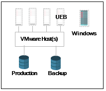
I like to first start out with the main site.
If you are using virtualization, then show your hosts, VMs, and your storage. Also, show any physical systems you may have.
Main Site
Now start listing any other sites that need protecting with the backups and will be included in your DR plan.
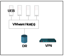
Once you have listed all of your remote sites you need to work on the DR site.
(This example will only use one site and a DR site)
Start by showing any hosts, VMs and storage you will be using.
Show any routers or VPN appliances that would be used for access to the DR site during a failover event.
DR Site
Draw the connections between sites to show how they will transfer data.
Don’t forget about listing your backup appliances.
Our main site is using the UEB Virtual appliance and utilizing a storage device on-site.
The DR site is using the UEB virtual appliance as well.
Main Site DR Site
![]()
This is a very basic diagram for this example and any level of detail can be obtained to meet your needs.
Once you have the picture drawn, you are going to want to get more detailed and list the all of the devices for each site that make up your infrastructure.
List all of your hosts and virtual machines by name.
List your networks used for production and DR testing, your storage, any physical servers and any backup appliances.
You should also list your connection speeds for all of the site links.
My example site we will work with throughout the series will be made up of the following:
| Main Office* ESXi host 1 * ESXi host 2 * Virtual Machines + DC1 + Exch 1 + SQL 2 + App 1 + File 1 + UEB-Main * Networks + VM Network + DR Sandbox * Storage + Production SAN + Backup SAN * Physical SQL server | DR Site* ESXi host 1 * Virtual Machines + UEB-DR * Networks + VM Network + Management + DR Sandbox * Storage + Production SAN + Testing SAN |
|---|
Applications
ReliableDR is designed to protect applications and not just individual virtual machines. An application can be made up of one or more virtual machines that all communicate with each other to present the application.
We have an Exchange application, which is made up of DC 1 and Exch 1.
We also have a CRM application made up of DC 1, SQL 2 and App 1.
There is a File Services application including DC 1, File 1, and the Physical SQL server from the main site.
These applications will be set up as separate jobs in ReliableDr. You want to look for common servers in each application. Here we see that DC 1 is needed in each application. We consider that a dependent server and can create a new job called a Continuous Dependency job with DC1 in the job. Now DC 1 can be removed from the other jobs and will run in its own job. The difference between a Continuous Dependency job and a regular job is that the server is left up and running in the DR sandbox after the test completes, so it is available to all other jobs.
| Applications | RPO and RTO |
|---|---|
| Continuous Dependency* DC 1 | RPO 6hr RTO 30min |
| Exchange* Exch 1 | RPO 6hr RTO 30min |
| CRM* SQL 2 * App 1 | RPO 24hr RTO 30min |
| File Services* File 1 * Physical SQL Server | RPO 6hr RTO 30min |
In our site diagram above we can start to think about our SLAs for the different applications.
We’ll go over a brief definition of RPO and RTO.
RPO, or Recovery Point Objective, is the point in time to where you want to be able to recover to. In other words, how much data are you willing to lose, or how frequently do you need to run backups?
RTO, or Recovery Time Objective, is the time it takes to recover. How long will it take to spin up that application?
The CRM application has an RPO of 24 hours and an RTO of 30 minutes. Exchange and File Services have an RPO of 6 hours and an RTO of 30 minutes. We can schedule these two jobs to run every 6 hours. Exchange can be scheduled to run every 24 hours. Note that DC 1 is common to all applications, so we need to set that job to run every 6 hours to match the RPO of CRM and File Services even though Exchange relies on DC 1 as well and only has an RPO of 24 hours.
Things to note: This example is using the Unitrends Enterprise Backup to protect the servers and copy them to the DR site. We need to make sure we schedule the Unitrends Enterprise Backup jobs to run as frequently as the RPO required. The ReliableDR jobs run on a separate schedule and should be set to run when the copy of data has completed for each server being protected.
This is enough for one day, and we’ve gotten the most important part completed. The diagram is the best way to visualize what you have in your environment and how the components will all work together to achieve Recovery Assurance for your applications.
The next installment of the Recovery Assurance series using ReliableDr will focus on implementing ReliableDR into the environment and going over the placement of the ReliableDR server.
Recovery Assurance Series
Part 1: How to Design a DR Plan Using ReliableDR
Part 2: Where should I Deploy the ReliableDR Server?
Part 3: How to Configure ReliableDR
Part 4: What Job is Right For You?